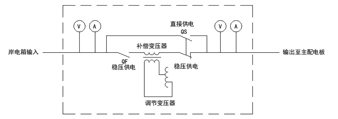
The shore power voltage stabilizer is mainly composed of a voltage stabilized power supply circuit breaker, a direct/stabilized power supply transfer switch, a compensation transformer, a voltage regulator, a voltage stabilizer controller, a special power acquisition module, a special temperature acquisition module and a display screen.
The voltage regulator circuit is composed of three-phase compensation transformer, three-phase voltage regulating transformer, voltage detection unit, servo motor control and transmission mechanism, protection circuit, etc. The primary winding of the voltage regulating transformer is connected in a Y shape and is connected to the output end of the voltage stabilizer, the secondary winding is connected to the primary winding of the compensation transformer, and the secondary winding of the compensation transformer is connected in series in the main circuit.
The voltage regulation process is: according to the change of the output voltage, the voltage detection unit samples, detects and outputs the signal to control the rotation of the servo motor, drives the brush group on the voltage regulating transformer to slide (or roll), and adjusts the secondary voltage of the voltage regulating transformer. , in order to change the polarity and size of the compensation transformer, and realize the automatic stabilization of the output voltage within the allowable range of the voltage stabilization accuracy, so as to achieve the purpose of automatic voltage stabilization.
When the voltage stabilizer fails or is in an emergency, it can be directly switched to direct power supply through the power supply transfer switch, and the input power of the shore power box can directly supply power to the main switchboard.
The block diagram of the working principle of the shore power voltage stabilizer is shown in Figure 2-1:
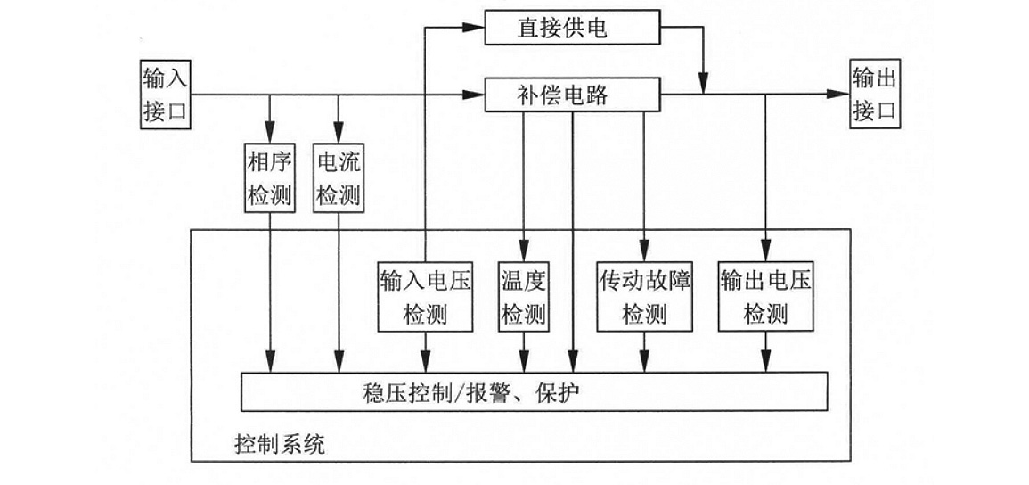
 The functional flow diagram of the shore power voltage stabilizer is shown in Figure 2-2:
 The functions of the main components of the shore power voltage stabilizer are as follows:
a) Compensation transformer: When the magnitude and polarity of the voltage applied to the primary coil changes, the secondary coil connected in series with the load loop can generate a compensation voltage transformer with variable amplitude and polarity.
b) Voltage regulating transformer: The voltage regulating transformer is a three-phase autotransformer that can automatically adjust the secondary voltage. It has two pairs of brushes that automatically slide symmetrically. The servo motor drives the brushes to slide along the exposed part (on the slideway) of the cylindrical winding of the autotransformer through the chain, and adjusts the secondary voltage smoothly to change the compensation voltage and maintain the stability of the output voltage.
c) Voltage regulation servo control circuit: There are two control modes of the voltage regulation servo motor: "manual" and "automatic". The manual and automatic mode selection is performed by the mode selection switch on the door. In the "manual" mode, the output voltage should be increased and press "Up" Press the "Pressure" button, to reduce the output voltage, press the "Pressure" button until the output voltage meets the requirements. In "automatic mode", the step-up and step-down detection units are automatically controlled to achieve automatic voltage regulation.
d) Voltage detection and adjustment unit: detect and adjust the sampling voltage on the printed circuit board, take out the sampling voltage and control voltage from the output end of the voltage stabilizer, after voltage transformation, rectification, filtering and voltage stabilization, the upper limit is obtained by the microcontroller comparator. and lower limit and reference voltage. The electrical signal of the sampling voltage changing with the output voltage is compared in real time by the single-chip microcomputer. When the output voltage changes beyond the allowable range of the setting accuracy, the voltage detection will issue a command to adjust the output voltage, and the relay or thyristor electronic switch action will drive the motor to adjust the voltage accurately. Until the output voltage is restored to the allowable range of the setting accuracy in an instant.
e) Over-limit protection device: Over-limit protection is set in the voltage automatic compensation system. The over-limit protection consists of limit switches. When the brush slides to both ends and collides with the limit switches, its normally closed contacts are disconnected and the servo motor stops.


