The power distribution safety monitoring system monitors and displays the working status and electrical parameters (current, voltage, etc.) of the load circuit breaker through the power distribution monitoring and acquisition module installed in the power distribution board, and uploads the monitoring data to the power monitoring system.
How it works
Through the monitoring module installed in the load switch, the electrical parameters such as the voltage and current of the load and the switch status are collected in real time. And through the RS485 interface, it is transmitted to the PLC control system in the form of MODBUS bus. After data processing, it will be displayed in the HMI, and the monitoring data will be transmitted to the power monitoring system through the RS485 interface.
2.3.1 Load monitoring loop
The monitoring and acquisition module collects the switch status, voltage and current parameters of the load and converts and processes the data, and transmits the monitoring data to the PLC controller for data processing in the form of a MODBUS bus with a 2-wire RS485 interface.
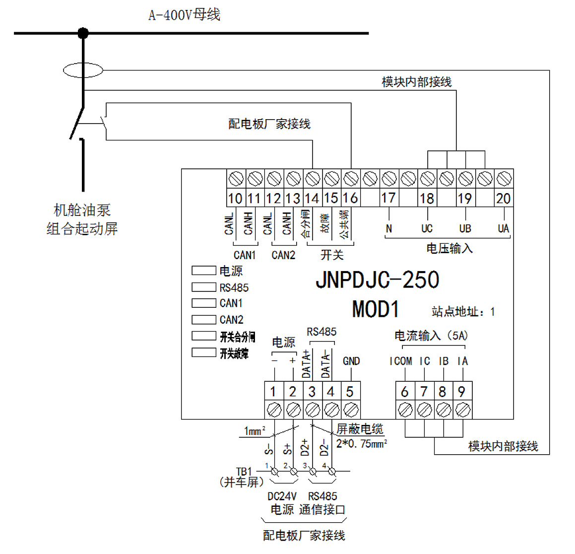
Figure 2-1 Load monitoring circuit
2.3.2 Control and display loop
The PLC controller receives the monitoring data of each load through the RS485 interface and performs conversion processing, and communicates with the HMI in real time through the Ethernet interface. The HMI can monitor the switch status, electrical parameters and communication status of the load in real time. At the same time, the PLC controller uploads the processed data to the power monitoring system (integrated network platform) in the form of an RS485 interface.
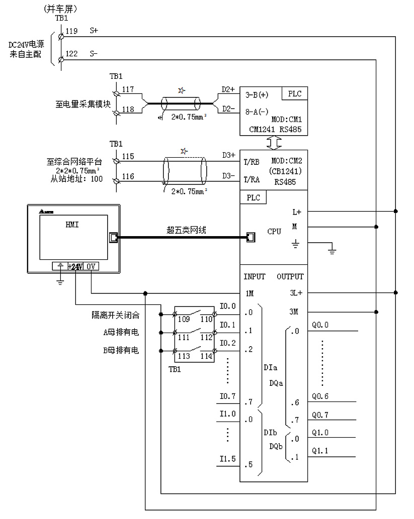
Figure 2-2 Control and Display Loop
2.3.3 Human-machine interface design
The power distribution safety monitoring system is equipped with a touch screen and a friendly man-machine interface. The operator can intuitively observe the working state of the load switch, the live state of the busbar, voltage parameters, current parameters, power (active and reactive), frequency, power factor and Communication status and other information. Since the ship needs to monitor a large number of load switches (27), multiple pages are set to display, each page displays the monitoring data of 3 load switches, and each page is set with "previous page" and "next page" respectively. page” to turn the page.
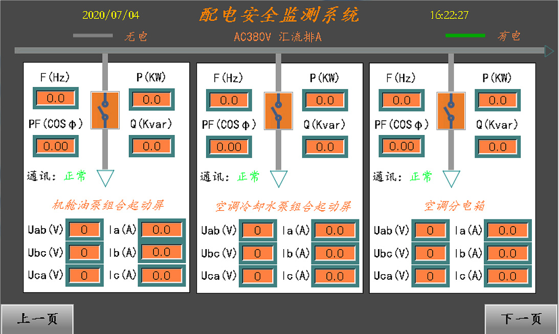
Figure 2-3 HMI display


